Overview#
| Board | Model | Main role |
|---|---|---|
| Main Controller Board | RBE-MAIN-RK3588S | Application computing, motion scheduling, and power distribution; connects joints and peripherals. |
| Rear-Interface Board | RBE_PWR_ |
USB, Ethernet, and power interfaces; manages the auxiliary-battery branch. |
| USB3.0 Flexible Interconnect | FPC | Provides a high-speed USB3.0 link between the main controller and rear-interface board. |
| IMU Board | RBE-SENS-IMU | Supplies orientation and motion feedback for balance control. |
| Head Interaction Board | RBE-PWR-HEAD | Connects cameras, microphones, speakers, and a MIPI display. |
| Hand Adapter Board | RBE-PWR-HANDPlusPro | Adapts the hand wiring harness to the main controller and end-effector interface. |
| Auxiliary-Battery Protection Board | RBE-PWR-HOTSWAP | Supports backup-battery charging and discharging, supplying the rear-interface board when main power is interrupted. |
| Motor Capacitor Board | RBE-PWR-MCAP | Provides local energy storage, absorbs spikes, and stabilizes the motor power bus. |
| Fan Power Board | RBE-PWR-FAN | Powers the hip cooling fans and controls their speed. |
| Battery Adapter Board | RBE-PWR-MINGMEI-BC | Adapts battery connections. |
| Charger Board | RBE_PWR_ |
Manages charging of the 48V main battery. |
| Logo Light Board | LAMP | Provides logo status indication, powered and controlled by the main controller. |
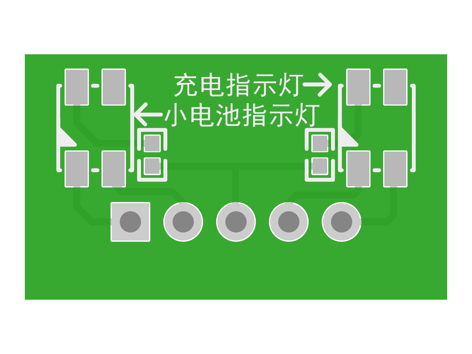
| Rear Power Indicator Board | INDICATOR | Displays power and charging status. |
| RBE-COMM-433TX | RBE-COMM-433TX | Operation and status channel. |
Understand System Roles Through the Boards#
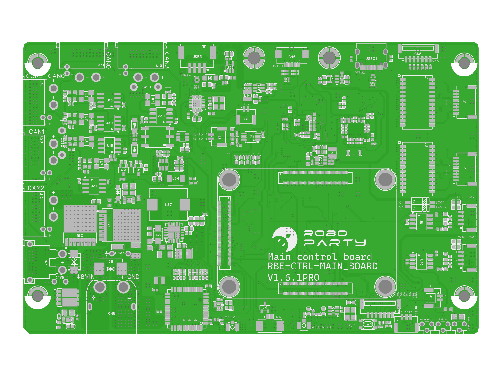
Main Controller Board#
Computing and interconnects · RBE-MAIN-RK3588S · Part number YCL.E000278 · Design revision V1.6.1pro
The hub for computing, motion scheduling, and power distribution. The application processor handles vision, speech, and inference tasks, while the real-time control unit manages motion scheduling and power sequencing; the two work together with distinct responsibilities.
Exchanges commands and status with joint drivers over CANFD, receives IMU feedback, and connects the head and rear-interface modules.
Rear-Interface Board#
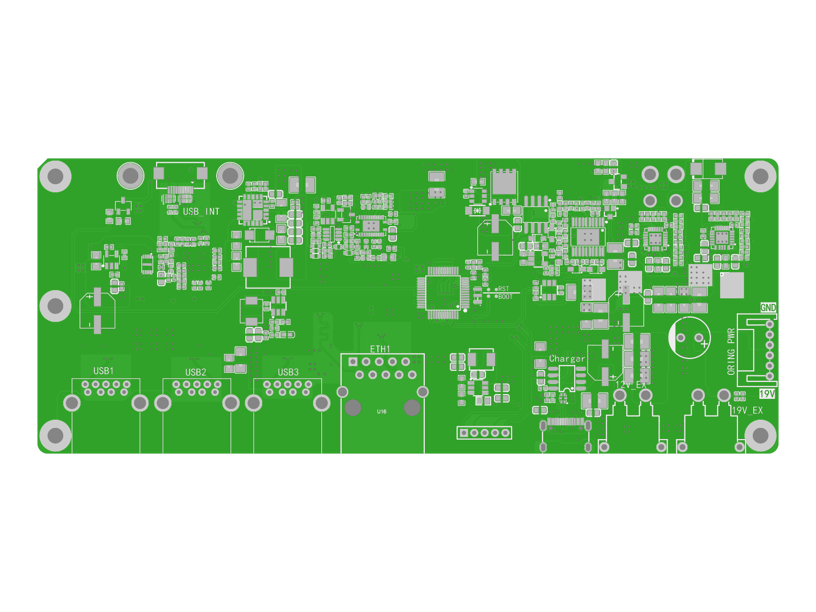
Computing and interconnects · RBE_PWR_BACKHUB · Part number YCL.E000191 · Design revision V2.1
Brings together expansion-device interfaces and power paths, providing USB, Ethernet, and multiple power interfaces, and manages charging and discharging of the 30V auxiliary-battery branch.
Connects to the main controller through USB3.0 FPC and Gigabit Ethernet. The architecture includes an optional Jetson NX expansion position.
USB3.0 Flexible Interconnect#
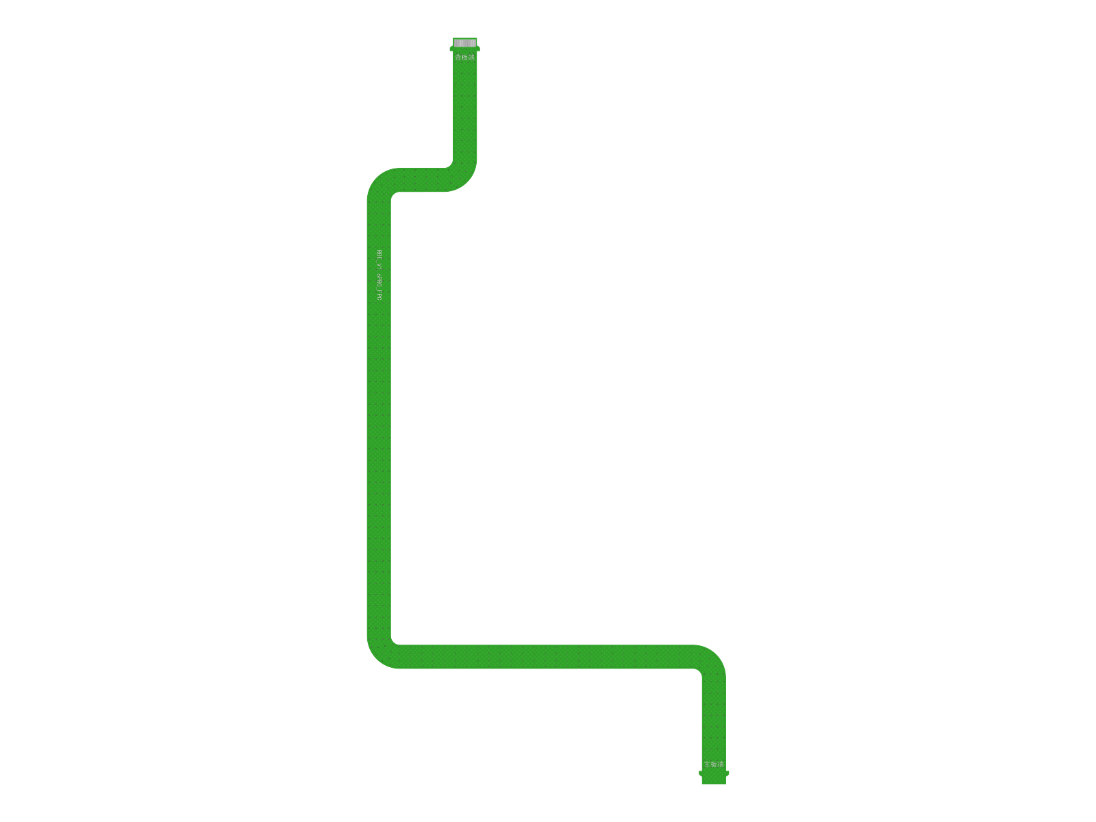
Computing and interconnects · FPC · Part number YCL.E000270 · Design revision V1.0
A high-speed differential link between the main controller board and rear-interface board, establishing a USB3.0 connection between the two system hubs.
Connects to: main controller board and rear-interface board.
IMU Board#
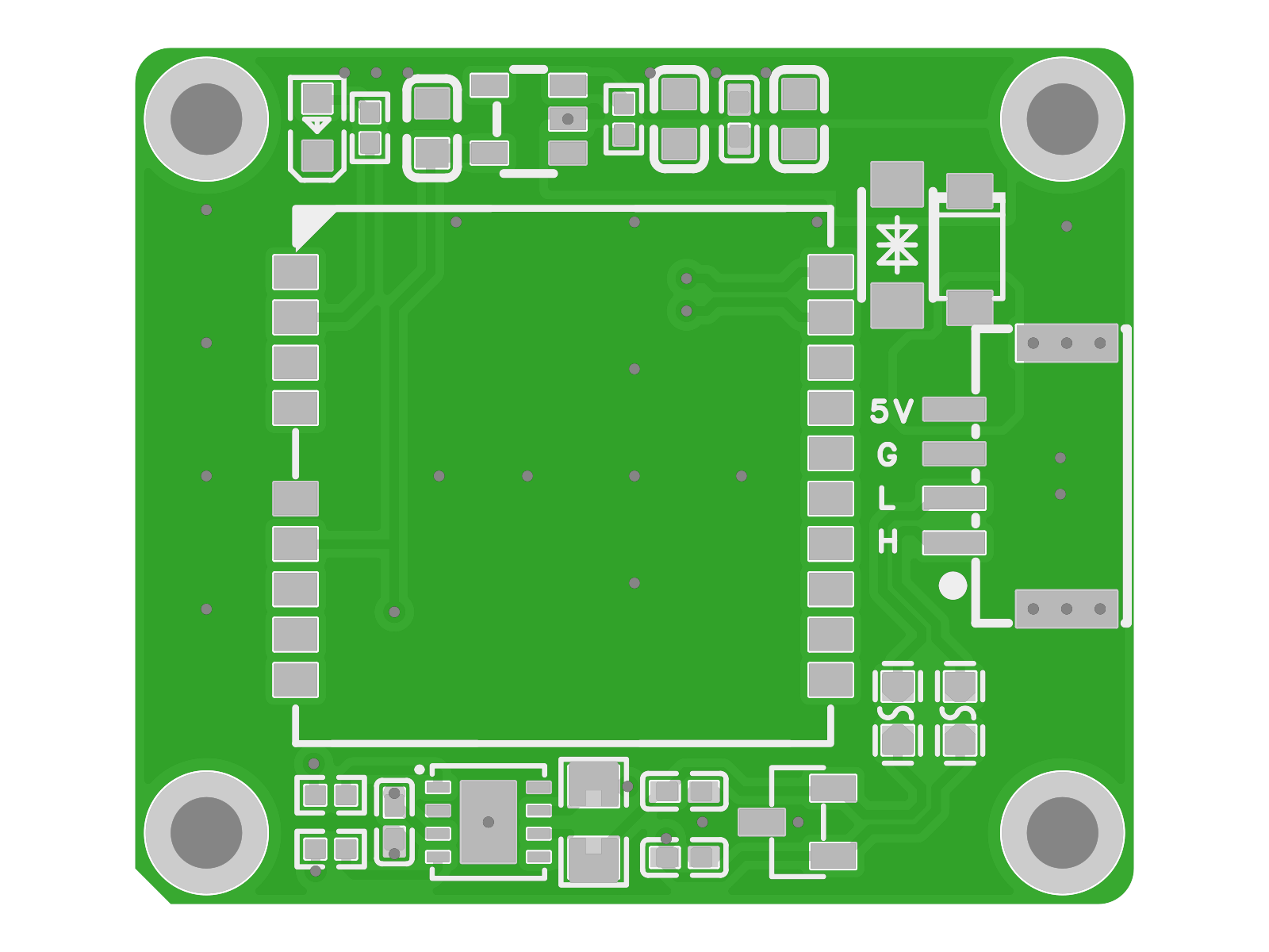
Perception and interaction · RBE-SENS-IMU · Part number YCL.E000059 · Design revision V1.0
Provides spatial orientation and motion feedback as perception input for bipedal balance control. It is positioned separately, away from motor power circuits.
Sends feedback to the main controller over a high-speed serial link.
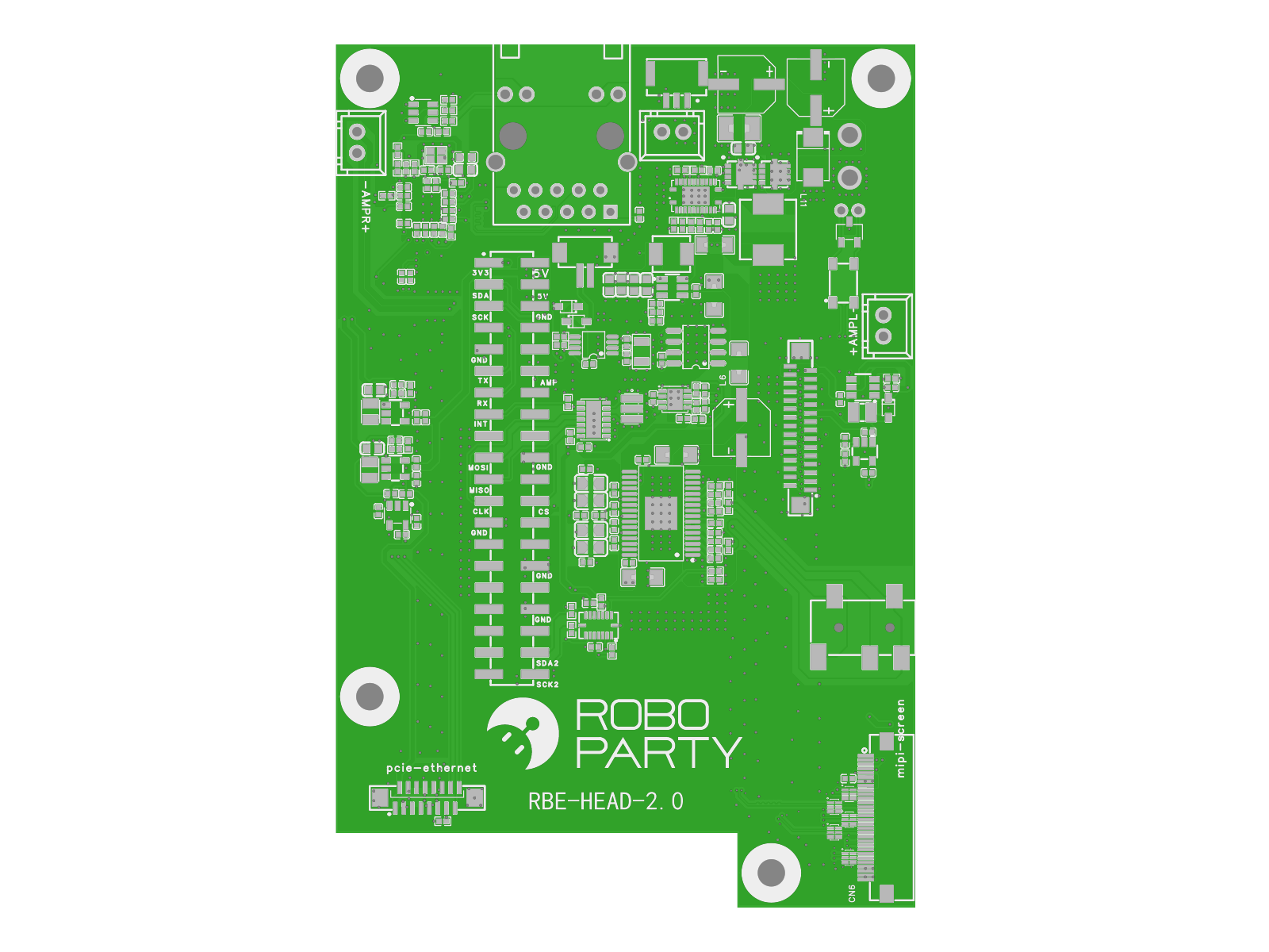
Head Interaction Board#
Perception and interaction · RBE-PWR-HEAD · Part number YCL.E000225 · Design revision V2.0
Connects cameras, microphones, speakers, and a MIPI display to form the head's vision, audio, and display interaction paths.
Camera video and preprocessed speech results are sent to the main controller through a high-speed data link.
Hand Adapter Board#
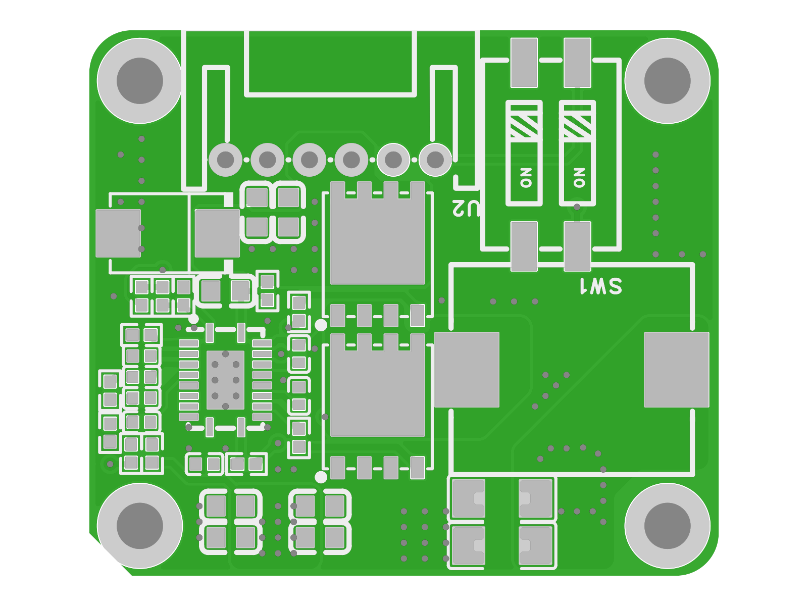
Perception and interaction · RBE-PWR-HANDPlusPro · Part number YCL.E000211 · Design revision V1.0
Adapts interfaces between the hand-joint wiring harness and the main controller, connecting the hand end effector to the robot's control interface.
Connects to: hand-joint wiring harness and main-controller interface.
Auxiliary-Battery Protection Board#
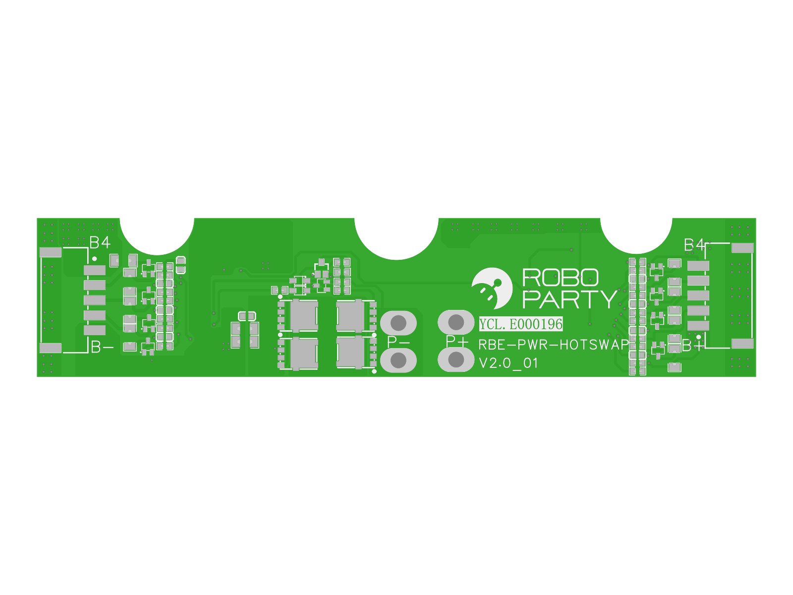
Power and status · RBE-PWR-HOTSWAP · Part number YCL.E000268 · Design revision V2.0
Located between the auxiliary battery and the rear-interface board, it participates in charging and discharging the backup power branch. When main power is available, it supports auxiliary-battery charging; when main power is interrupted, the auxiliary-battery branch supplies the rear-interface board.
Connects to: 30V auxiliary battery and rear-interface board.
Motor Capacitor Board#
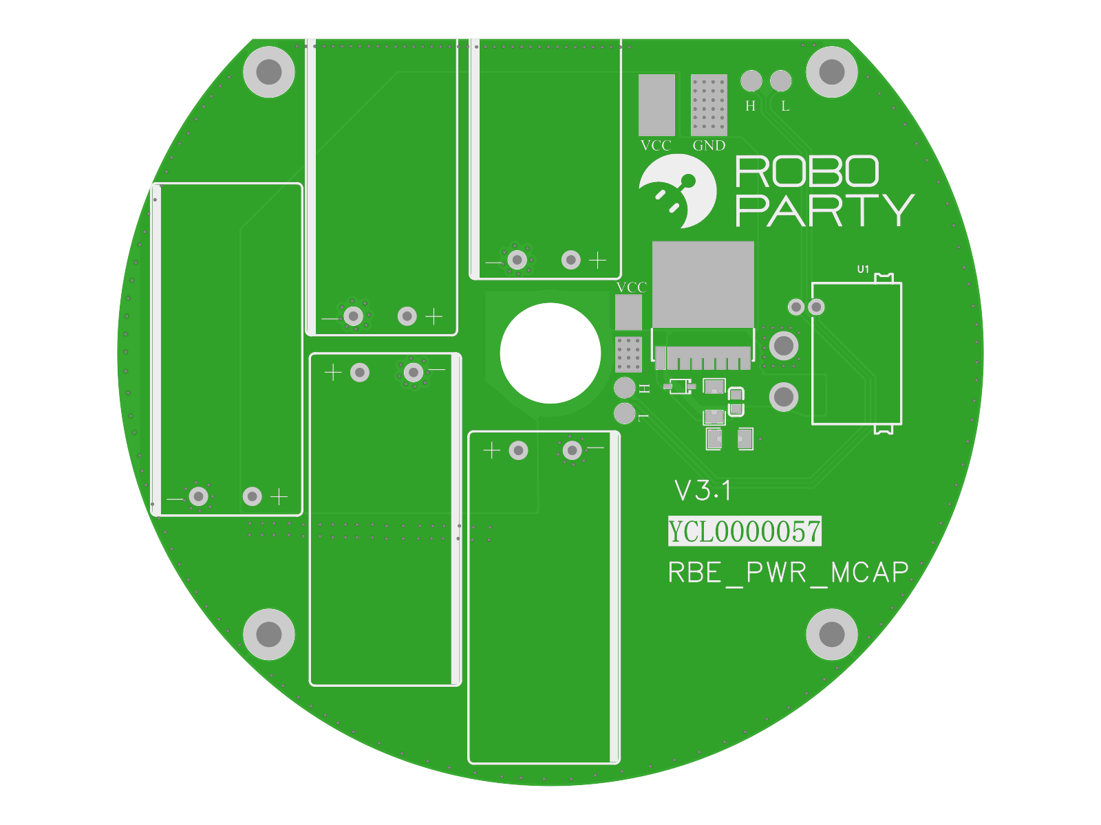
Power and status · RBE-PWR-MCAP · Part number YCL.E000057 · Design revision V3.1
Provides local energy storage near the motor, absorbing commutation spikes, stabilizing the bus voltage, and suppressing conducted interference.
Works with: motor and driver power circuits.
Fan Power Board#
Power and status · RBE-PWR-FAN · Part number YCL.E000062 · Design revision V2.0
Supplies power and speed control for the hip cooling fans as part of the body's thermal-management system.
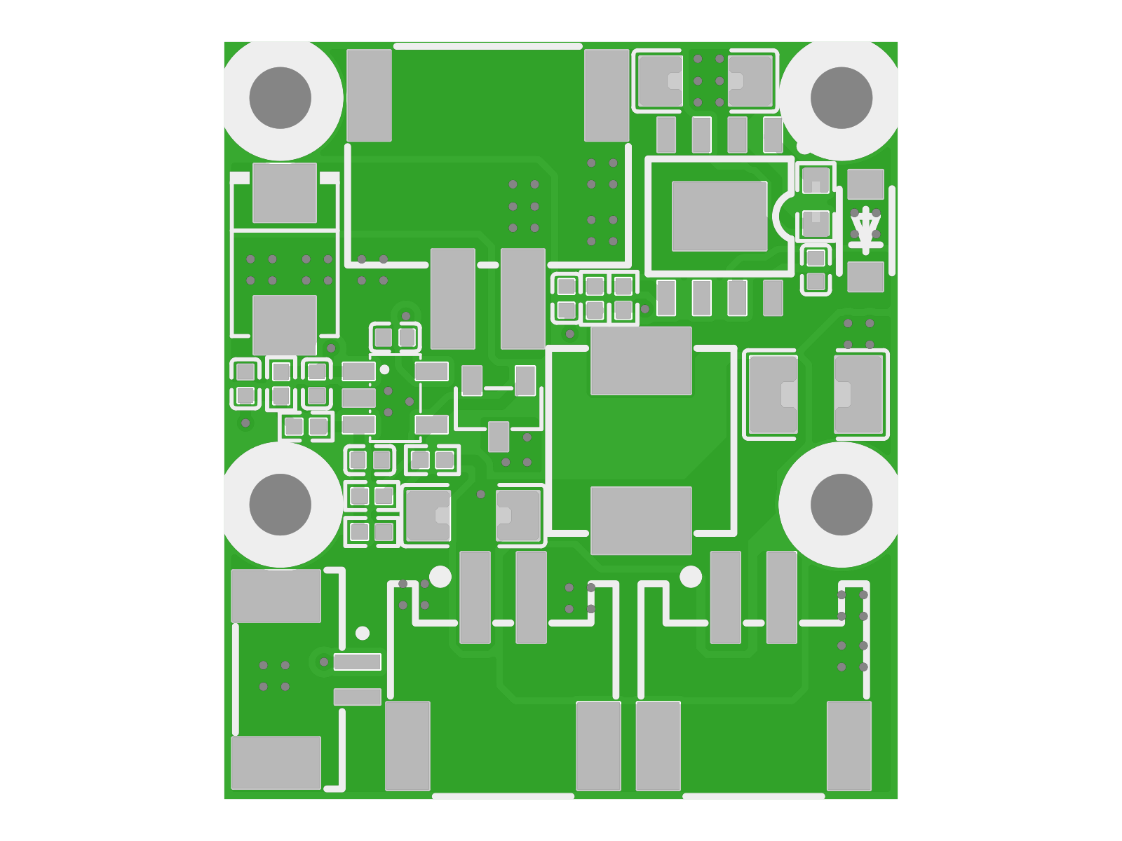
Battery Adapter Board#
Power and status · RBE-PWR-MINGMEI-BC · Part number YCL.E000060 · Design revision V1.1
Provides an adapter for battery connections.
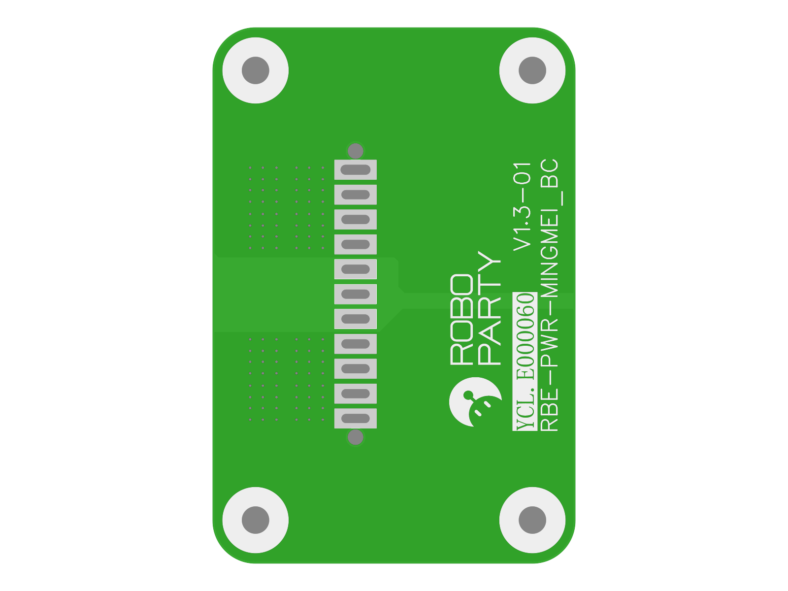
Charger Board#
Power and status · RBE_PWR_140WCHG · Part number YCL.E000223 · Design revision V1.0
Manages charging of the 48V main battery, forming the charging stage of the main power system.
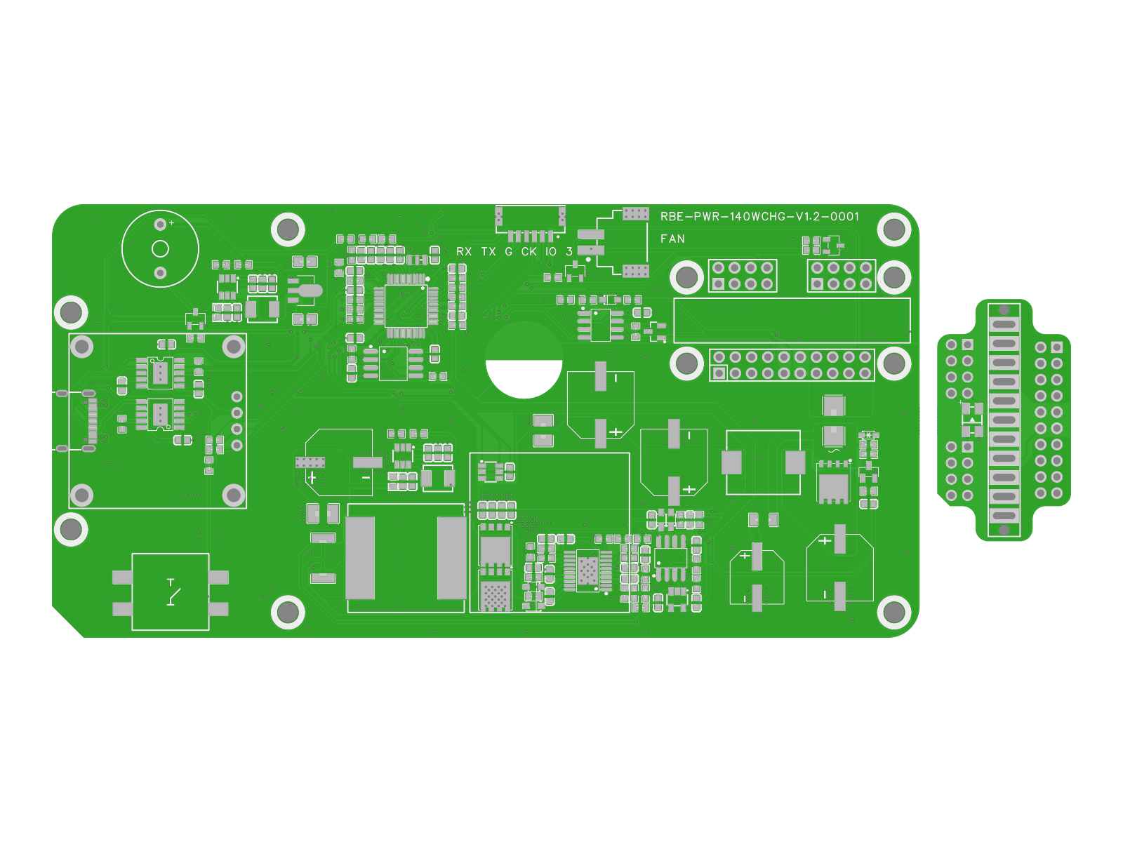
Logo Light Board#
Power and status · LAMP · Part number YCL.E000063 · Design revision V2.0
Provides logo status indication, powered and controlled by the main controller.
Control path: GPIO / PWM.
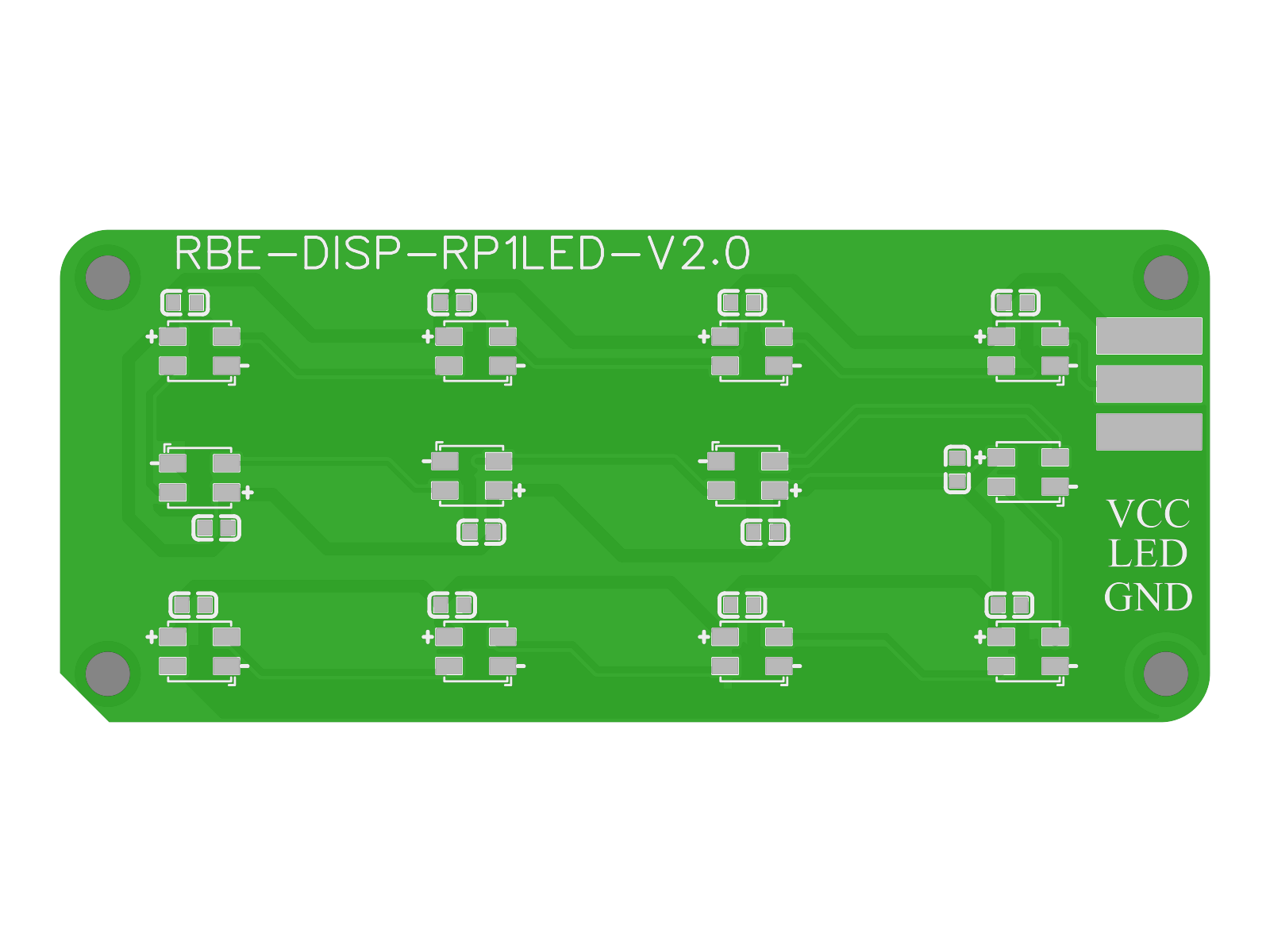
Rear Power Indicator Board#
Power and status · INDICATOR · Part number YCL.E000255 · Design revision V1.0
Turns power and charging status into externally visible indications.
RBE-COMM-433TX#
Communication board design · RBE-COMM-433TX · Part number YCL.E000212 · Design revision V1.0
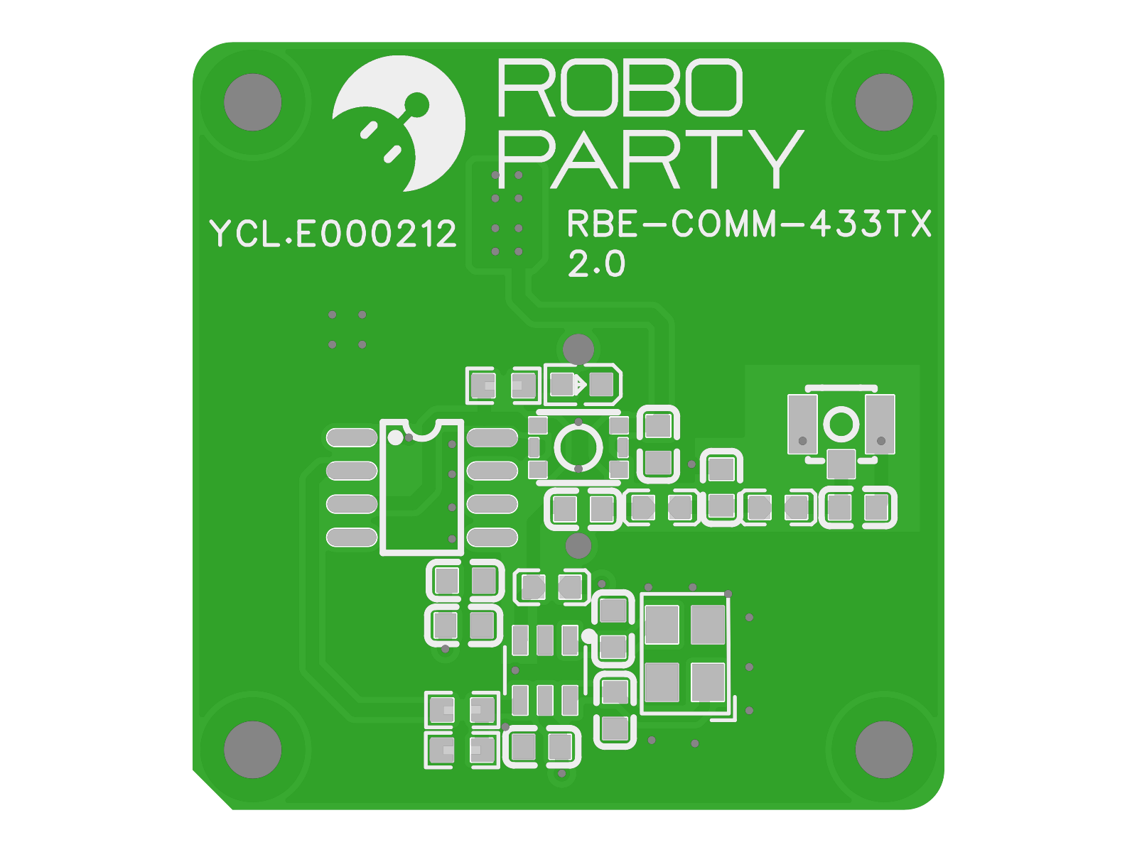
Board resources: 5966da24 · Installed options and quantities are defined by the corresponding whole-robot BOM.
System Connections#
The main controller and rear-interface board form the system hubs. Main power, the backup branch, and data/control links each have distinct roles.
Power Relationships#
| Connection | Link | Description |
|---|---|---|
| Charger board → 48V main battery | Main-battery charging | The charger board manages charging of the main battery. |
| 48V main battery → Main controller board | 48V main supply | The main controller manages power sequencing and distribution to modules. |
| 48V main battery → Rear-interface board | Direct 48V supply | The rear-interface board is powered directly by the main battery. |
| Main controller board → Actuators | Main-controller power supply | The main controller distributes power to motors and drivers. |
| Rear-interface board ↔ Auxiliary-battery protection board / 30V auxiliary battery | 30V charging/discharging | Normal charging and reverse power supply through the backup branch. |
Read the main-supply path and backup charging/discharging path separately. Moving highlights in the original diagram indicate direction only.
Data and Control#
| Connection | Link | Description |
|---|---|---|
| Head interaction board → Main controller board | High-speed data link | Uploads camera video and preprocessed speech results. |
| Main controller board ↔ Rear-interface board | USB3.0 FPC / Gigabit Ethernet | Connects interface expansion and system computing. |
| IMU ↔ Main controller board | High-speed serial link | Transfers spatial orientation and motion feedback. |
| Main controller board ↔ Motor drivers | 5 CANFD channels | Sends motion commands and receives status feedback. |
| Main controller board → Logo light board | GPIO / PWM | Controls status indication. |
| Rear-interface board ↔ Optional Jetson NX | PCIe / USB | Provides an expansion path for additional computing modules. |
| Emergency-stop input → Real-time control unit | Hardwired / 433MHz | Emergency-stop input path in the architecture. |
Connection arrows indicate direction; Jetson NX is an optional expansion. The emergency-stop path does not establish a safety rating or response time.
Computing and Real-Time Control Roles#
Application computing handles vision, speech, and inference; real-time control handles motion scheduling and power sequencing. CANFD connects the joint drivers, with commands sent out and status returned to form the control link.
Connecting Perception to the Motion System#
The IMU provides orientation and motion feedback, while the head connects vision and audio interaction. Sensor information reaches the main controller over the respective data links, and actuators perform local closed-loop control and motion execution.
Expansion Devices and Auxiliary Modules#
The rear-interface board connects expansion devices and backup power. Hand adapters, cooling, motor-side energy storage, and status indicators each perform local functions. Jetson NX is an optional computing expansion.
Mechanical Structure#
Mechanical designs are divided into common parts and parts specific to an upper-limb configuration. Select part models by whole-robot configuration, part number, and revision, then consult the corresponding engineering drawings and manufacturing requirements.
| Process | Entry point | Available resources |
|---|---|---|
| CNC | CNC part models | STEP parts for Common, 5DOF, and 7DOF |
| 3D printing | 3D-printed part models | Cable-clamp STEP models |
YCL.M000225 is the common waist Yaw stop ring, while YCL.M000341 is the 55 stop ring in the seven-DoF upper-limb directory. Downloads preserve the original STEP geometry and units; manufacturing also requires engineering drawings, the BOM, and manufacturing requirements for the corresponding revision.
Assembly and Wiring Harnesses#
Assembly designs organize parts by instance, part number, and position, while the whole-robot BOM lists materials and assembly levels. Exploded views and assembly/disassembly analysis must use the assembly CAD and corresponding BOM.
Wiring harnesses connect the main controller, drivers, sensors, and auxiliary modules. Wiring, power supply, fastening, and power-up procedures must use drawings and formal operating documents for the same configuration and corresponding revision.