Wire BOM Table#
| Number | Harness Type | Wire harness length | Number of wire harnesses | Remarks |
|---|---|---|---|---|
| RBW_Origin_Arm01 | XT30(+2)-F.G.B-XT30(+2)-F.G.B | 20cm | 2 | Double head 90 ° can line up and down |
| RBW_Origin_Arm02 | XT30(+2)-F.G.B-XT30(+2) -F.G.B | 20cm | 2 | 90 ° can line up and down * 2 |
| RBW_Origin_Arm03 | XT30(+2)-F.G.B-XT30(+2)-F.G.B | 20cm | 2 | Double head 90 ° can line in the same direction * 2 |
| RBW_Origin_Arm04 | XT30(+2)-F.G.B-XT30(+2)-F.G.B | 20cm | 2 | Double-ended 90° CAN line up and down *2 |
| RBW_Origin_Leg01 | XT30U-F-XT30U-F (gh1.25 2pin 反线 30cm) | 25cm | 2 | |
| RBW_Origin_Leg02 | XT30U-F-XT30U-F (gh1.25 2pin 反线 30cm) | 25cm | 2 | |
| RBW_Origin_Leg03 | XT30U-F-XT30U-F (gh1.25 2pin 反线 50cm ) | 40cm | 2 | |
| RBW_Origin_Leg04 | XT30U-F-XT30(+2)-F.G.B (gh1.25 2pin 反线 35cm) | 30cm | 2 | (2+2) end 90° |
| RBW_Origin_Leg05 | XT30(+2)-F.G.B-XT30(+2)-F.G.B 10cm | 10cm | 2 | 1: Side 90 ° (left) 2: Side 90 ° (right) During assembly, the orientation of the CAN line position shall be unified (up and down during welding) |
| RBW_Origin_Body01 | XT30U-F-XT30U-F (gh1.25 2pin 反线 30cm) | 20cm | 1 | |
| RBW_Origin_Body02 | XT30(+2)-F.G.B-XT30(+2)-F.G.B | 20cm | 2 | Single head 90 ° * 2 |
| RBW_Origin_Body03 | XT30(+2)-F.G.B - XT30U-F (gh1.25 2pin 反线 65cm) | 60cm | 1 | |
| RBW_Origin_Body04 | XT30(+2)-F.G.B - XT30U-F (gh1.25 2pin 反线 55cm) | 50cm | 1 | |
| RBW_Origin_Body05 | usb to typec | 1 | Support ubs3.0 | |
| RBW_Origin_Body06 | typec to typec | 1 |
Wiring section#
This robot adopts symmetrical structure design, and the wiring rules on the left and right sides are consistent. The following text only explains the wiring of the right leg and left hand , and the wiring method of the right hand and left leg is referred to. The waist is an independent wiring area, and the wiring method needs to be operated according to separate instructions.
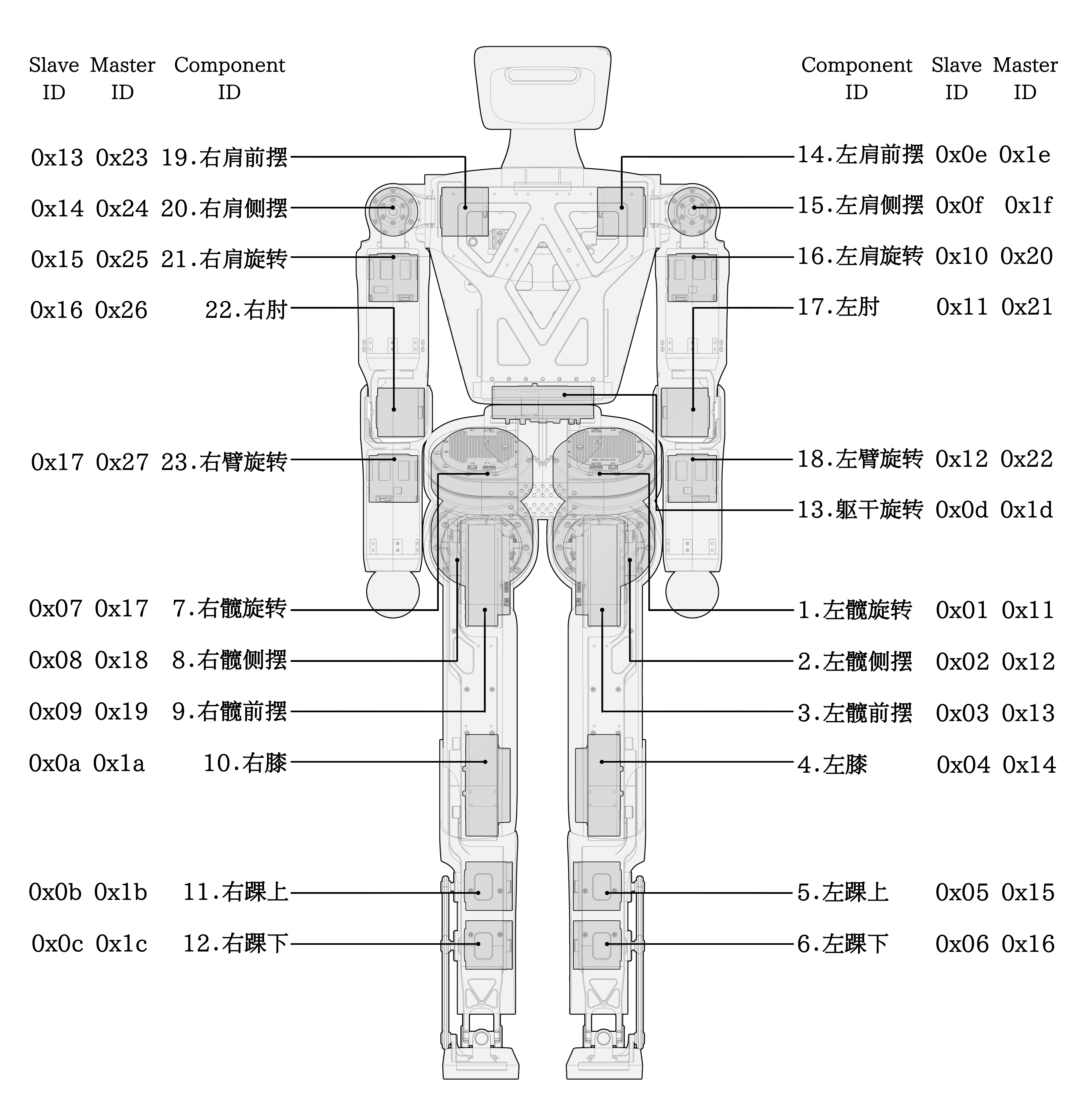
The following is Slave ID.
Wiring sequence: Right hand: 0x13-0x14-0x15-0x16-0x17, Left hand: 0x0E-0x0F-0x10-0x11-0x12, Right leg: 0x07-0x08-0x09-0x0A-0x0B-0x0C, Left leg motor connection sequence: 0x01-0x02-0x03-0x04-0x05-0x06, Waist motor: 0x0D-0x07.
2.1 Leg Wiring#
Motor 0x07–Motor 0x08: Select RBW_Origin_Leg01, with a specification of XT30–XT30 and a length of 25cm.
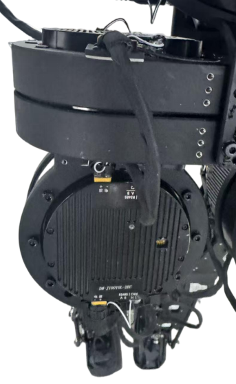
Motor 0x08–Motor 0x09: Select RBW_Origin_Leg02, with a specification of XT30–XT30 and a length of 25cm.
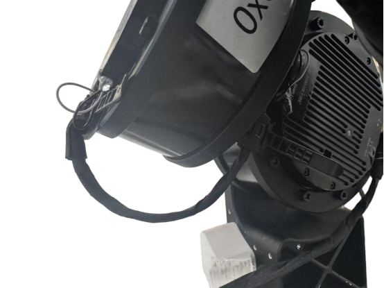
Motor 0x09–Motor 0x0a: Select RBW_Origin_Leg03, with a specification of XT30–XT30 and a length of 40 cm.
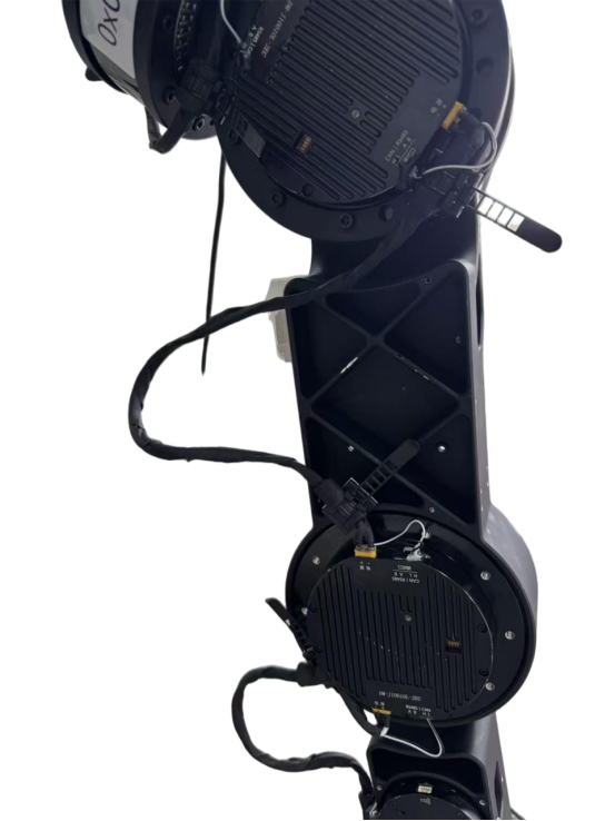
Motor 0x0a–Motor 0x0b: Select RBW_Origin_Leg04, with specifications XT30–XT30 (+2) and a length of 30 cm.
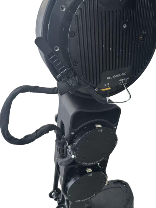
Motor 0x0b–Motor 0x0c: Select RBW_Origin_Leg05, with specifications XT30 (+2)–XT30 (+2) and a length of 10 cm.
2.2 Waist Wiring#
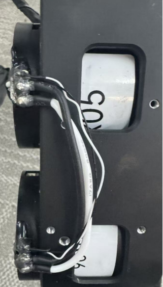
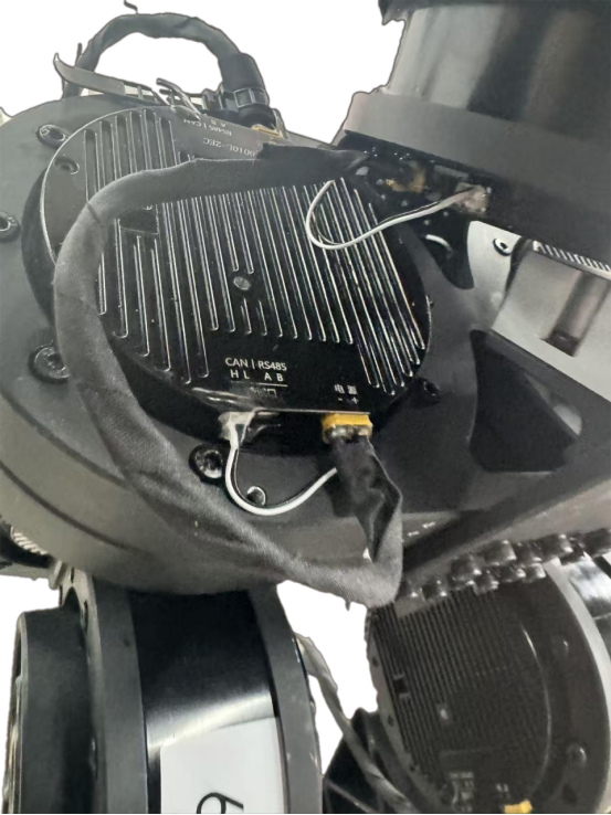
The waist has a total of one motor (ID: 0X0d) connected to the right leg motor 0x07
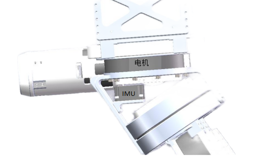
Motor 0x0d - Motor 0x07: Select RBW_Origin_Body01 , with a specification of XT30–XT30 and a length of 20 cm.
2.3 Hand Wiring#
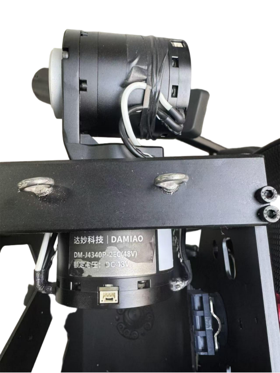
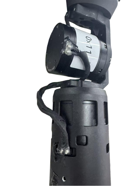
Motor 0x0e - Motor 0x0f: Select RBW_Origin_Arm01 wiring harness, specification XT30 (+ 2) - XT30 (+ 2), length 20cm.
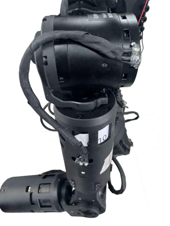
Motor 0x0f - Motor 0x10: Select RBW_Origin_Arm02 , with specifications XT30(+2)-XT30(+2) and a length of 20 cm.
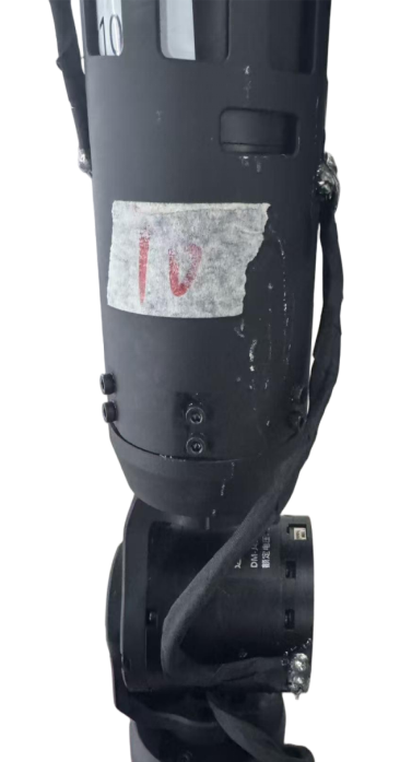
Motor 0x10 - Motor 0x11: Select RBW_Origin_Arm03 , with specifications XT30(+2)-XT30(+2) and a length of 20 cm.
Motor 0x11 - Motor 0x12: Select RBW_Origin_Arm04 , with specifications XT30(+2)-XT30(+2) and a length of 20 cm.
2.4 Battery Wiring#
Preparation of Screw Copper Pillars:
Screws: m316×2, m412×2, m5*12×2
Copper pillar: m3 * 17 × 4, m3 * 8 + 3 × 8
2.4.1 Battery Installation#
- Battery protection : paste shock-absorbing sponge pad at the bottom and around the battery.
- Objective: To buffer the high-frequency vibration in motion and prevent the risk of short circuit caused by the wear of the battery skin.
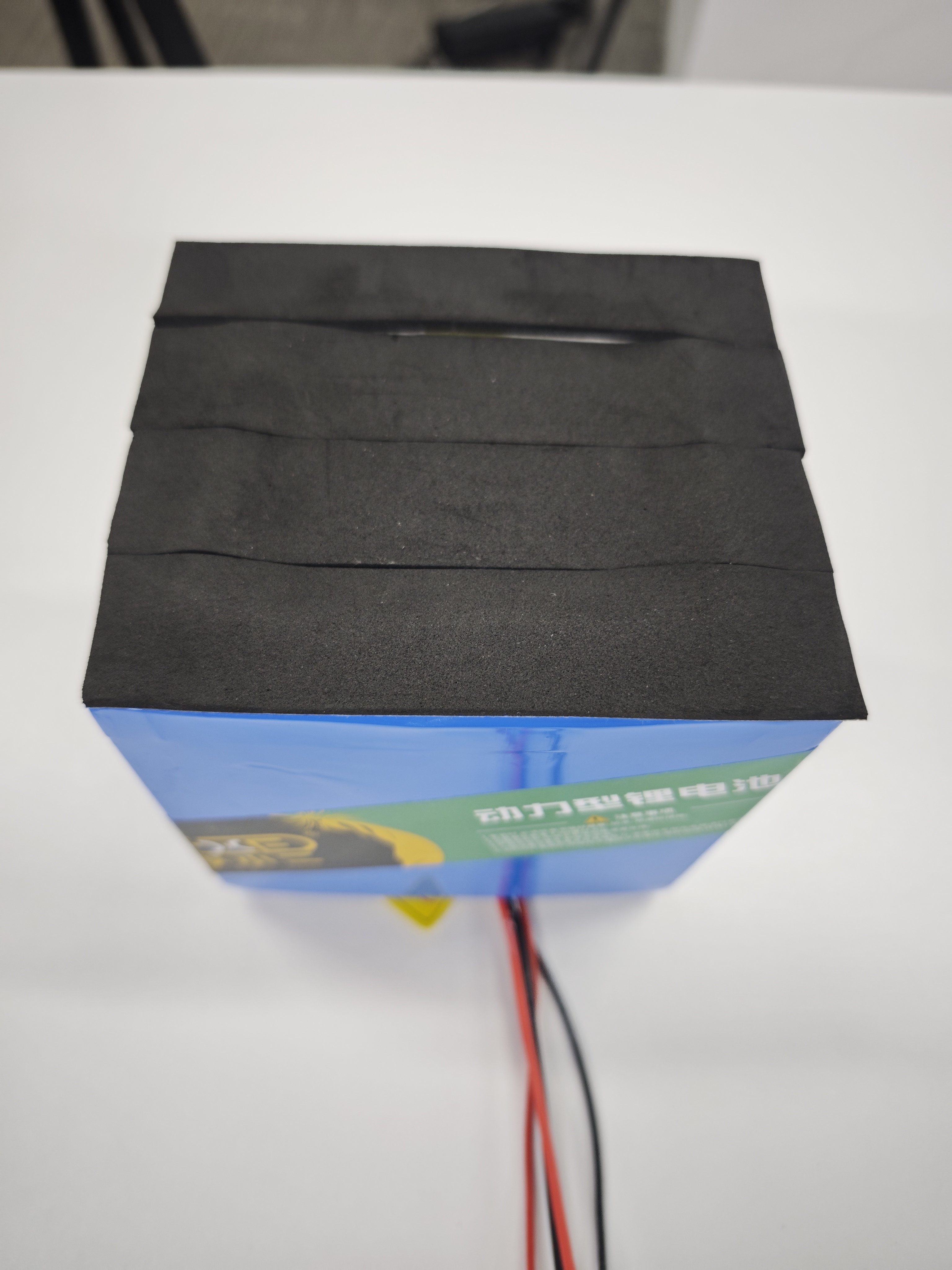
This stage involves high current circuits, please be sure to check the wire diameter and polarity.
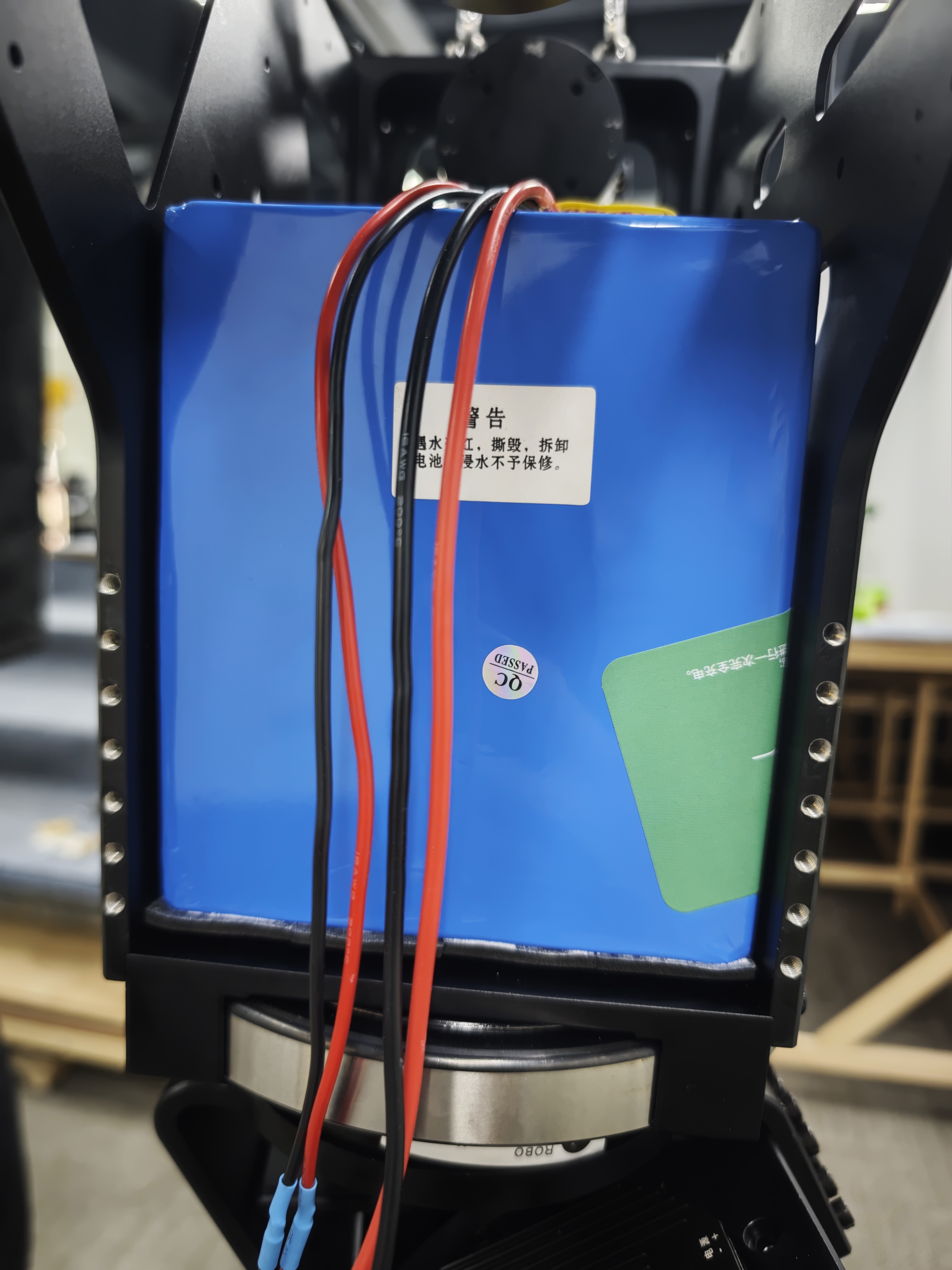
- Battery in place : Install the battery pack to the predetermined position of the base to ensure a stable center of gravity.
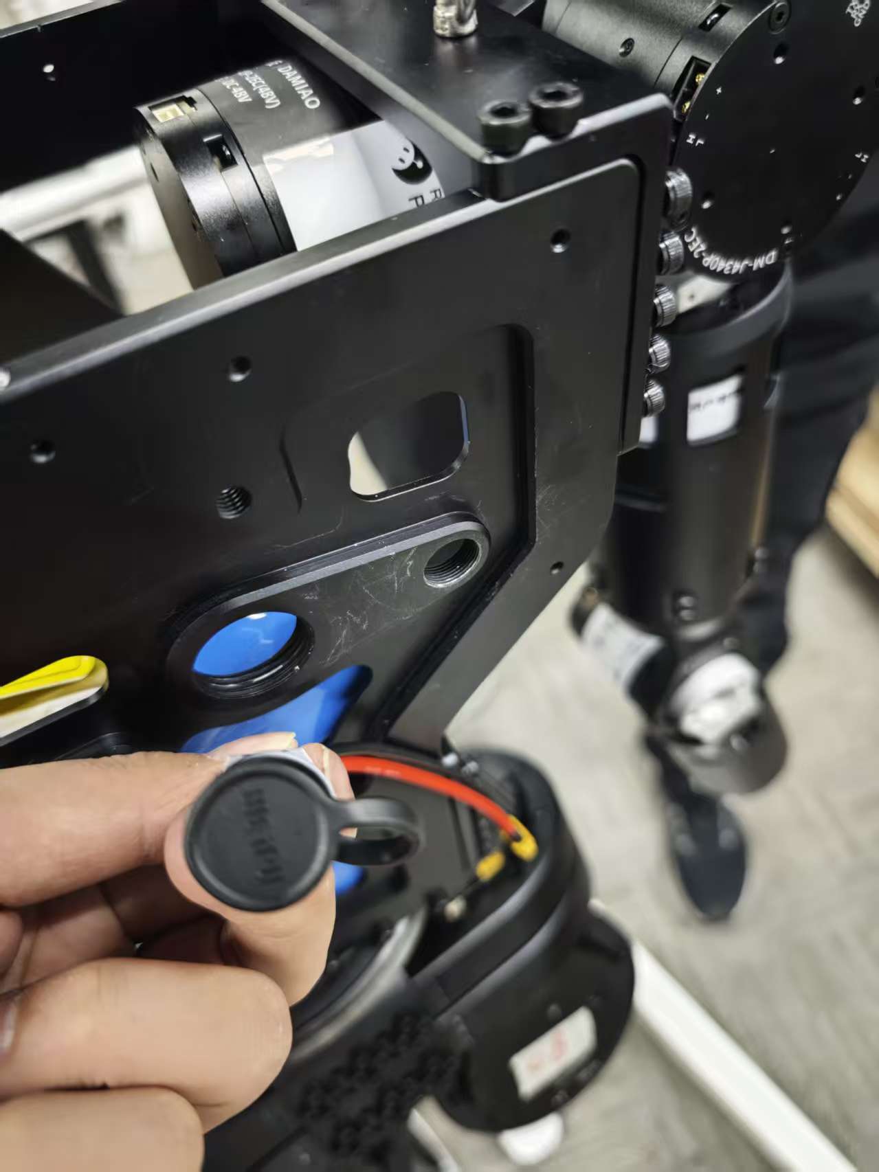
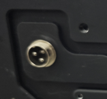
- Charging interface installation :
- Fix the charging port to the back panel of the robot.
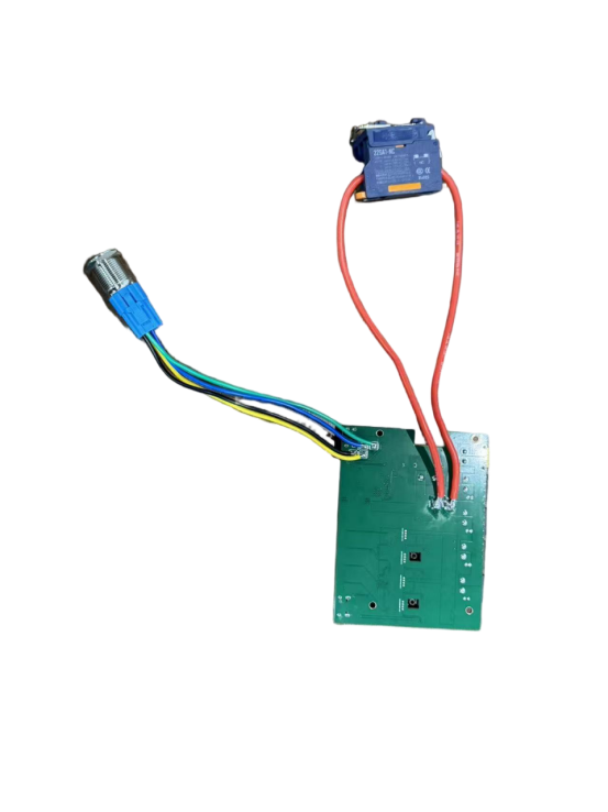
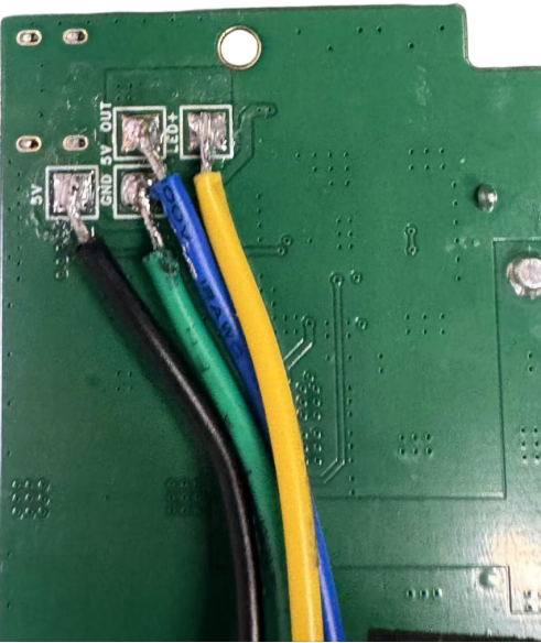
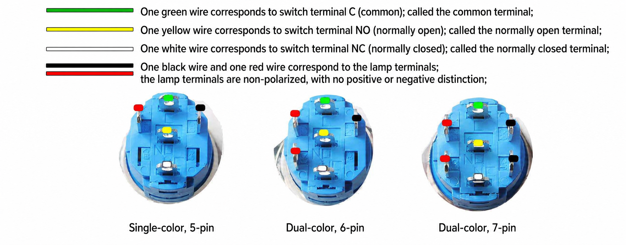
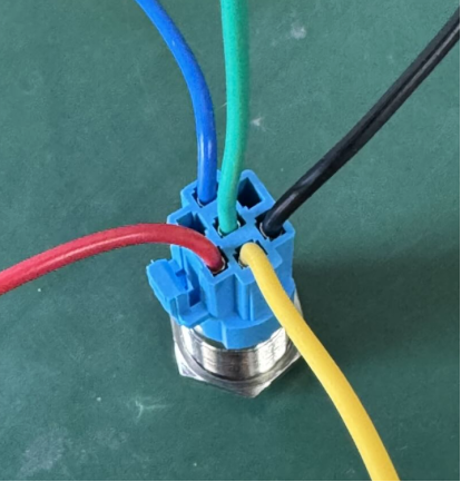
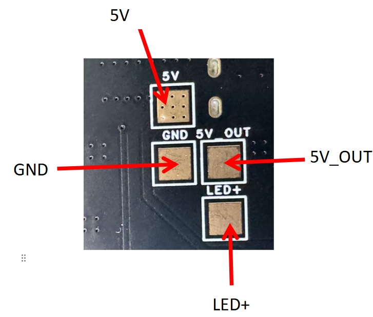
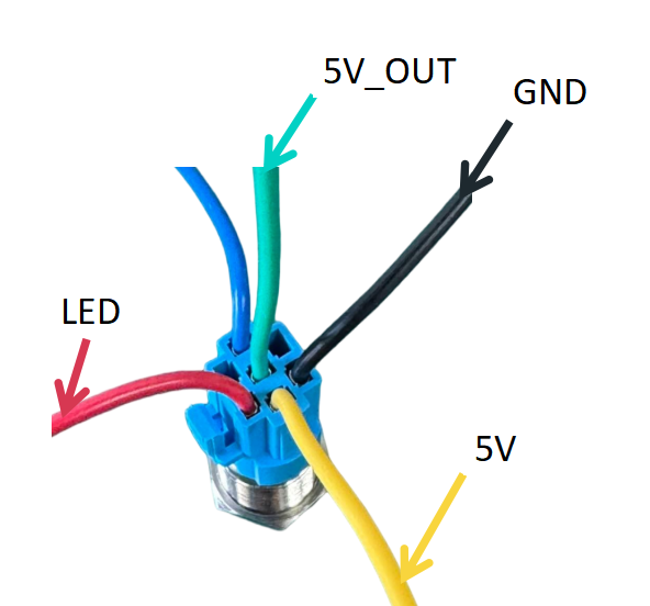
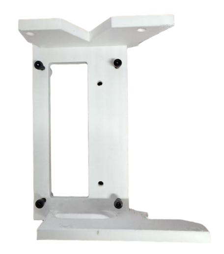
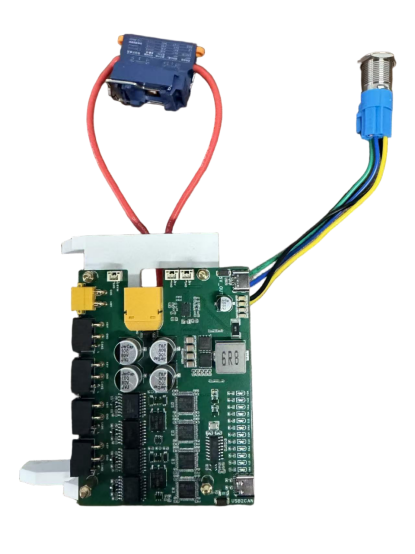
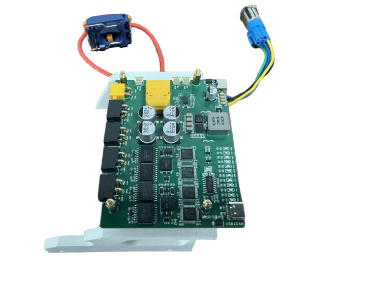
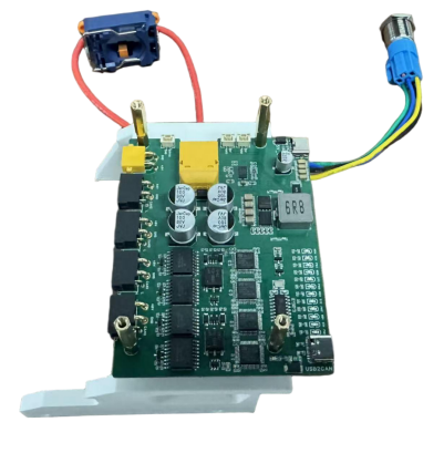
2.5 Main control connection#
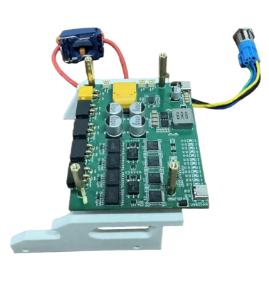
The other interface of motor 0x0e, motor 0x13, motor 0x01, and motor 0x07 is uniformly connected to RBE_Board_v2.0.
Motor 0x0e- power supply board: select RBW_Origin_Body02 , specifications are XT30 (+ 2) -XT30 (+ 2), length is 20cm.
Motor 0x13-power supply board: select RBW_Origin_Body02 , specifications are XT30 (+ 2) -XT30 (+ 2), length is 20cm.
Motor 0x01-power supply board: select RBW_Origin_Body03 , specifications are xt30 (+ 2) - xt30, length is 60cm.
Motor 0x0d-power supply board: select RBW_Origin_Body04, specifications are xt30 (+ 2) - xt30, length is 50cm.
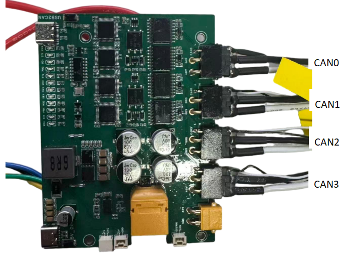
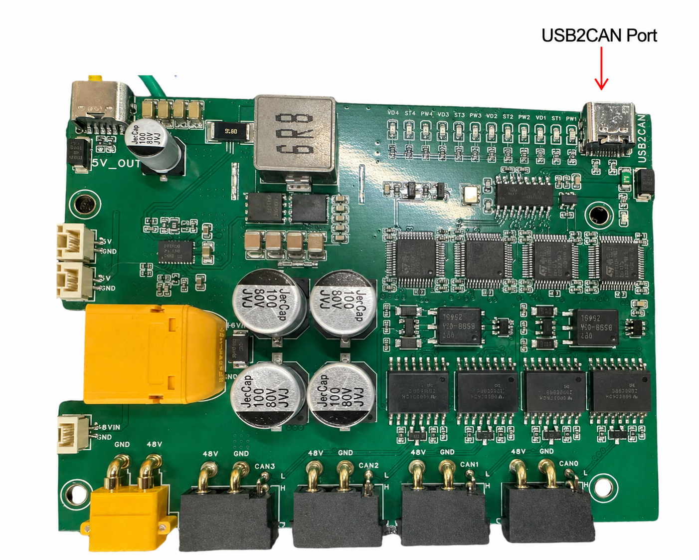
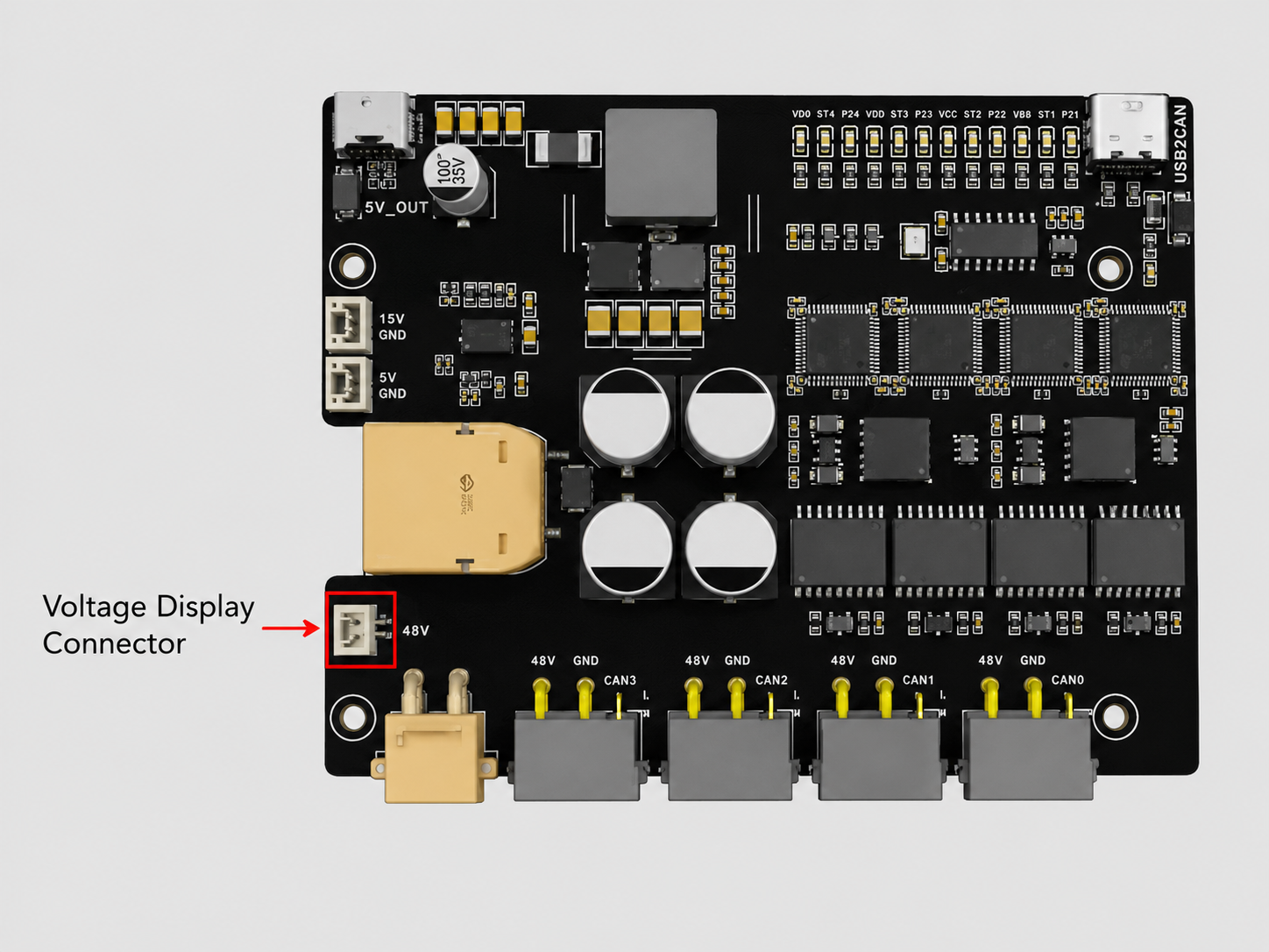
Motor connection power supply board follows the principle of first left then right, first leg then hand . Motor 0x01 corresponds to CAN0 , motor 0x0d corresponds to CAN1 , motor 0x0e corresponds to CAN2 , motor 0x13 corresponds to CAN3 .
2.6 Inter-board connection#
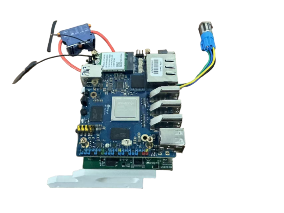
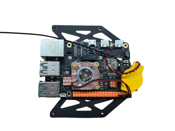
Here we provide both orange pie and RDKx5 board connection solutions, which can be used in combination with your own situation during actual operation.
- Orange Pie wire harness connection
Orange Pie uses RBW_Origin_Body05 , which connects to the USB-to-CAN interface on the carrier board through the USB 3.0 interface;
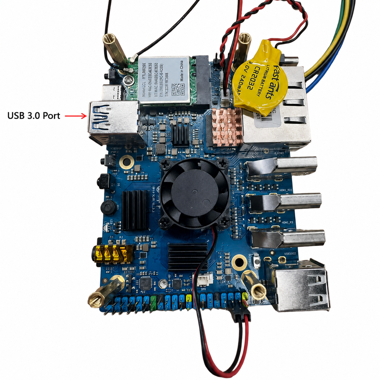
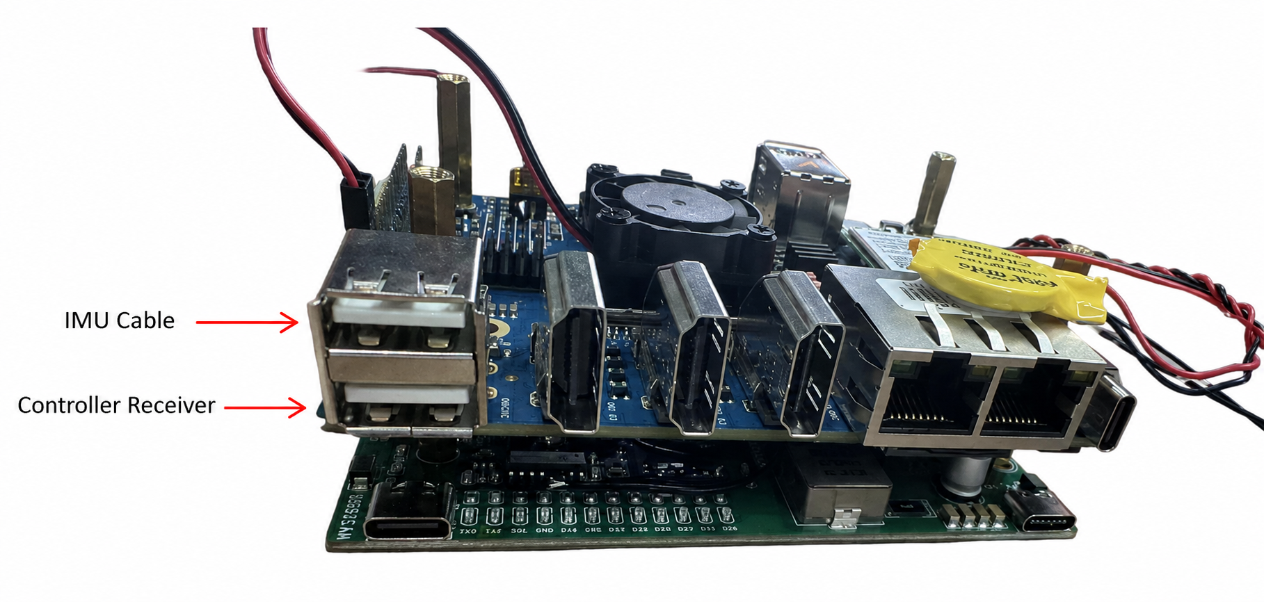
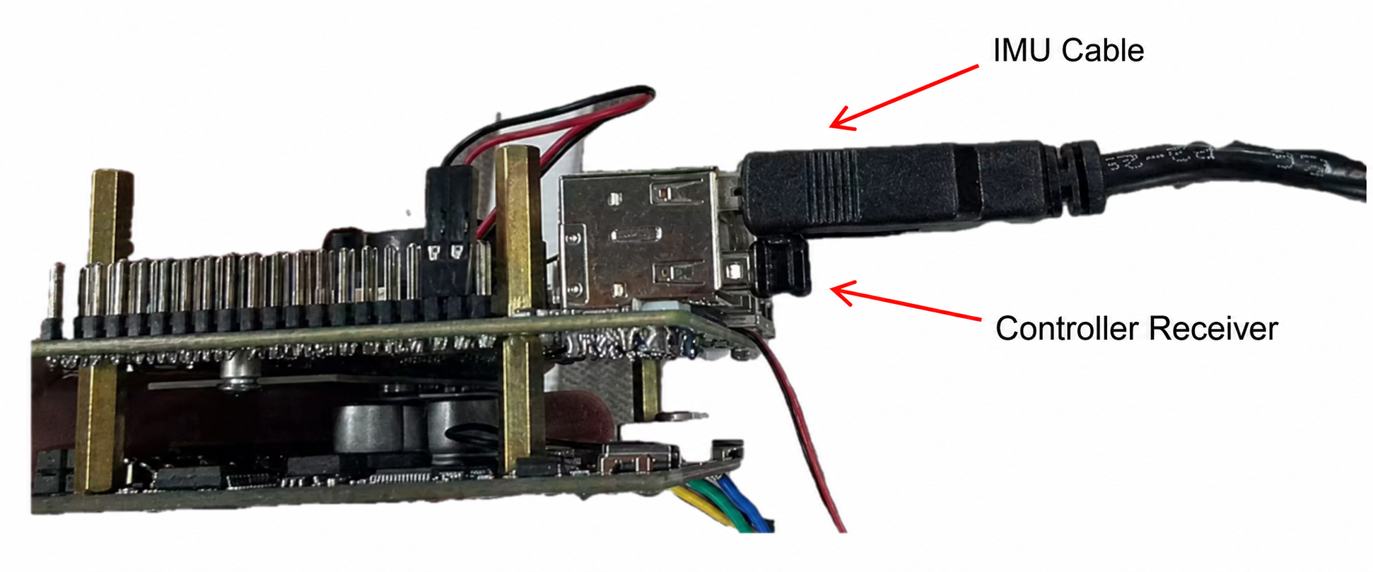
The IMU and handle receiver are directly connected to the Orange Pie via a USB 2.0 interface.
- RDKx5 connection
RDKx5 uses RBW_Origin_Body05 , and connects to the USB-to-CAN interface on the carrier board via the USB interface;
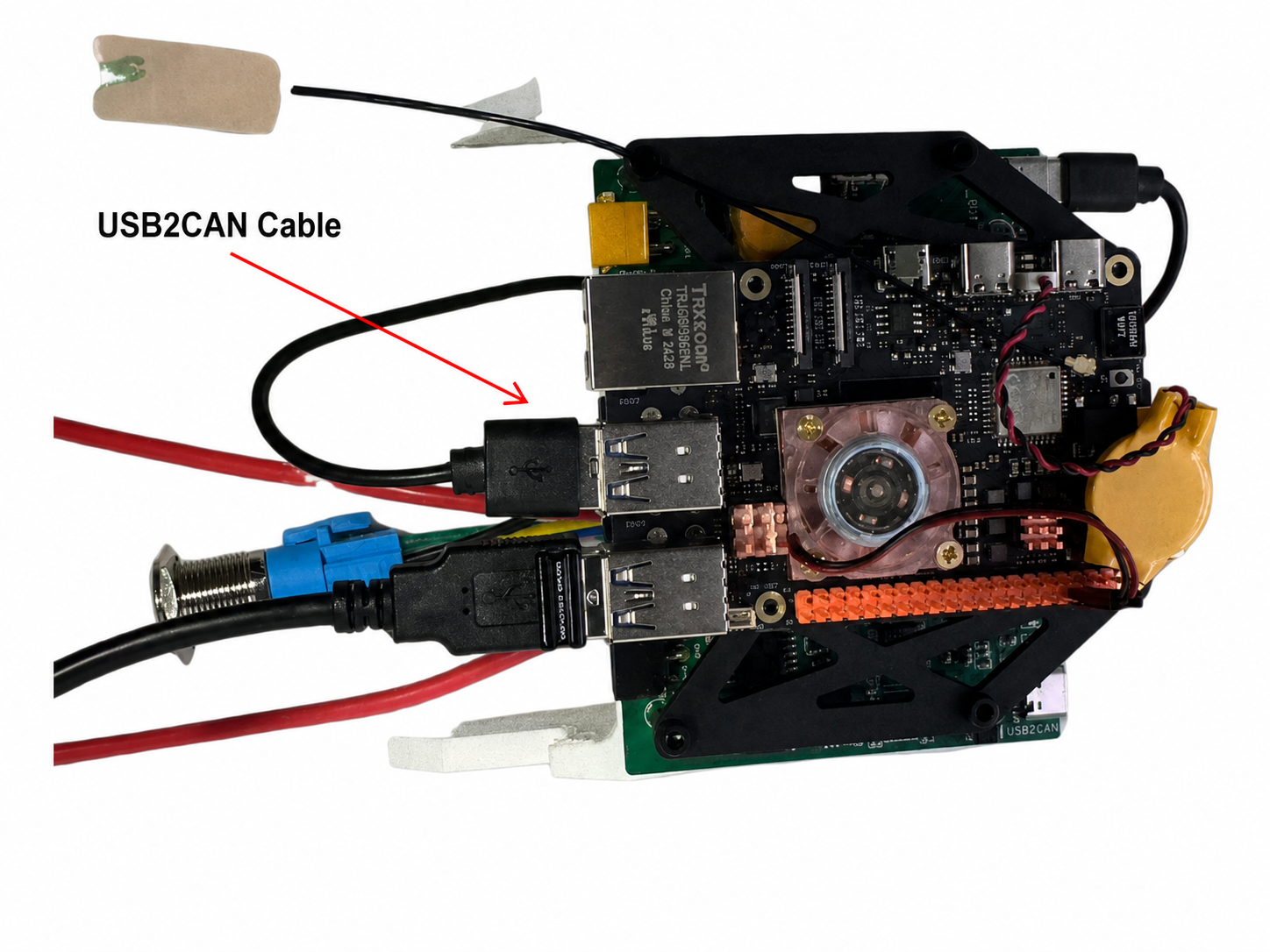
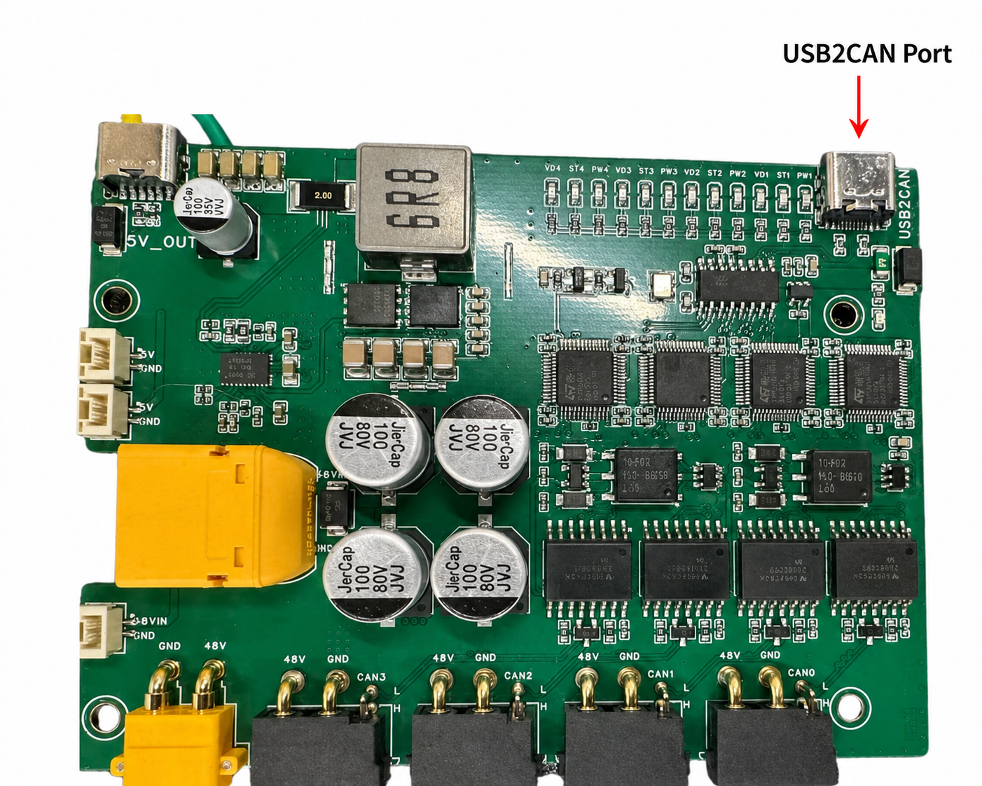
The IMU and handle receiver are directly connected to the RDKx5 via the USB interface.
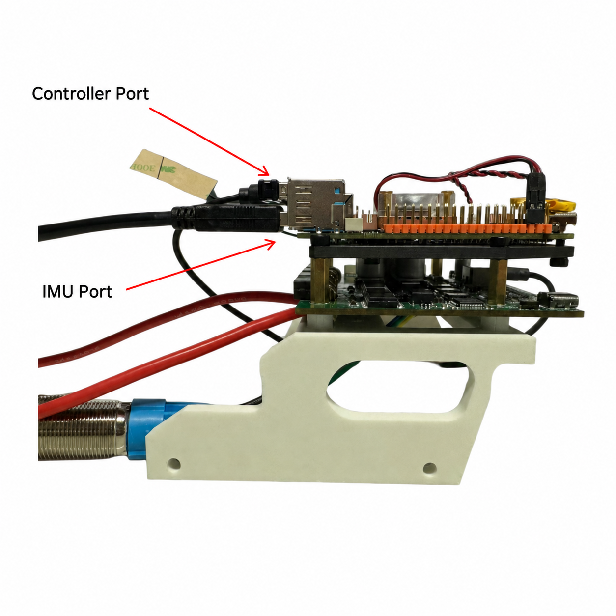
- Voltage display meter connection
The voltage display connection port is gh1.25.
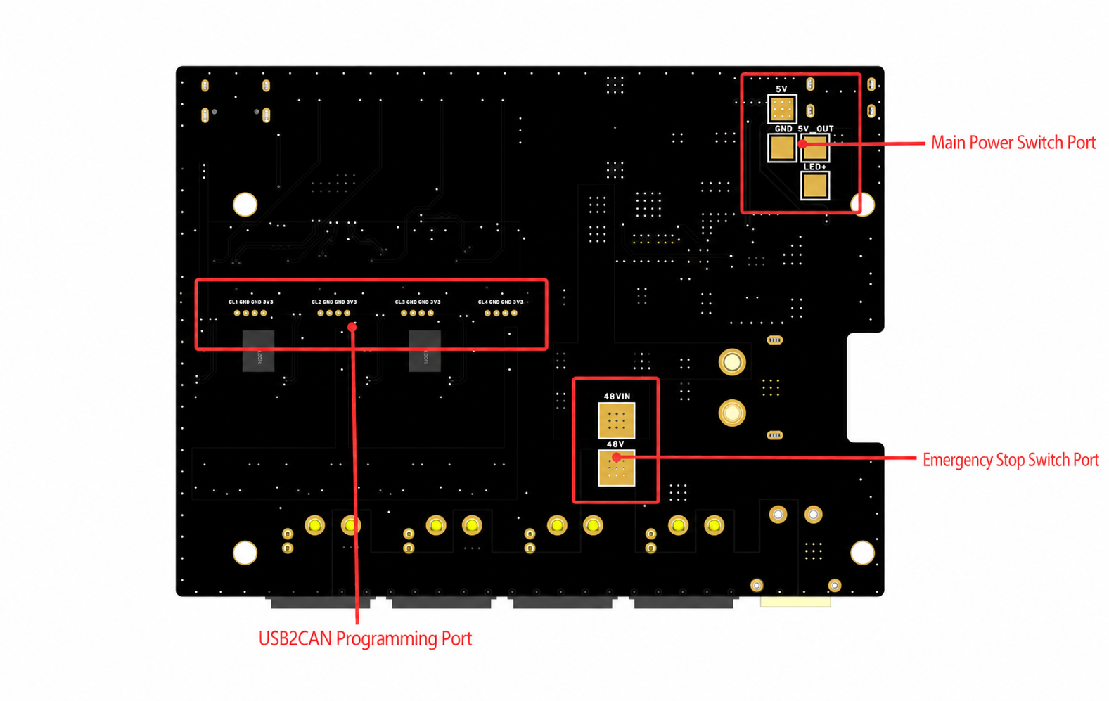
The interface layout and definition of the three-in-one board are shown below. Please strictly refer to the silk screen logo when connecting to avoid reverse connection.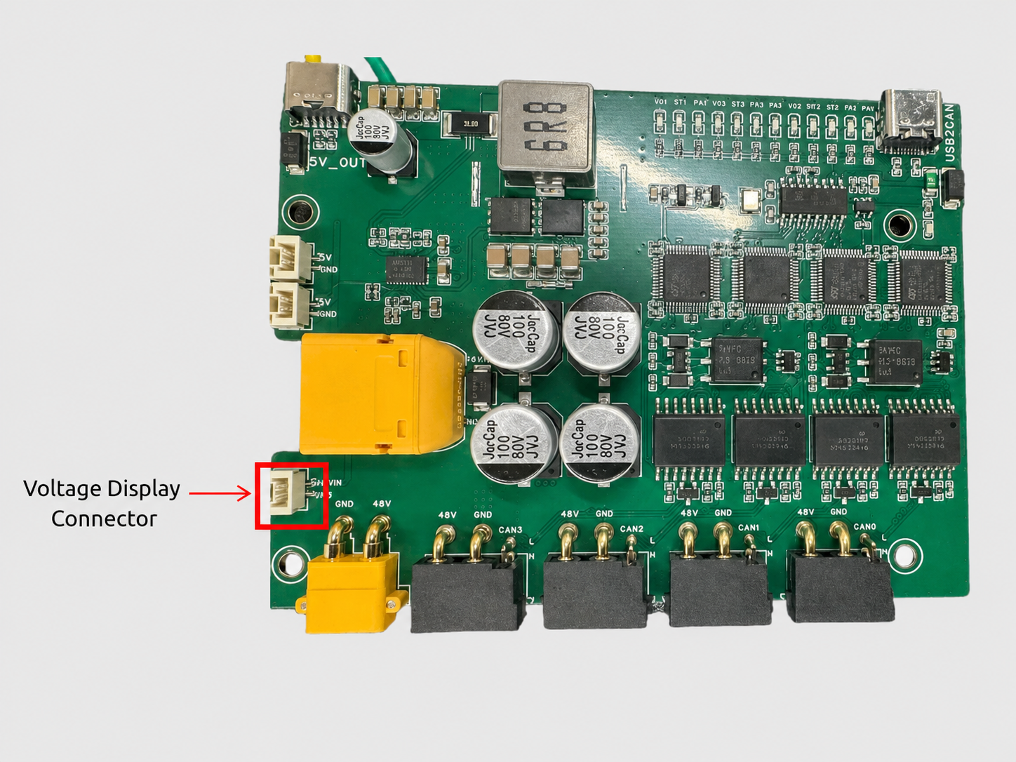
Fixed portion#
3.1 Wire harness fixation#
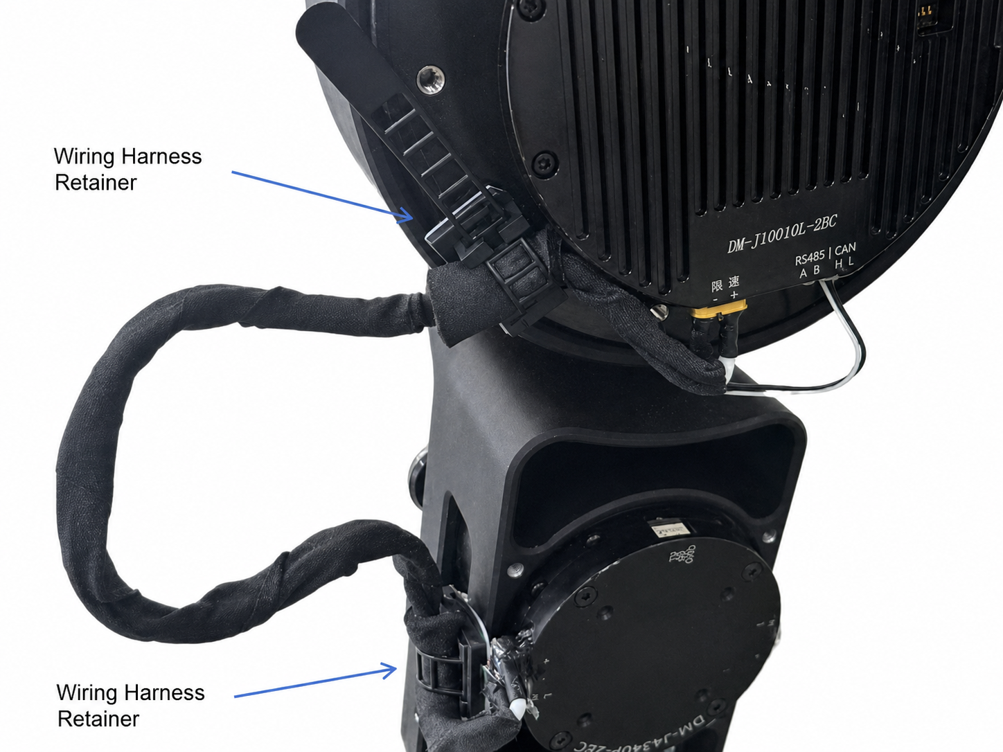
Wire harness fixing method: The wire harness holder is used to fix the port of the wire harness to prevent unstable signal transmission caused by loose port.
3.2 Port Fixing#
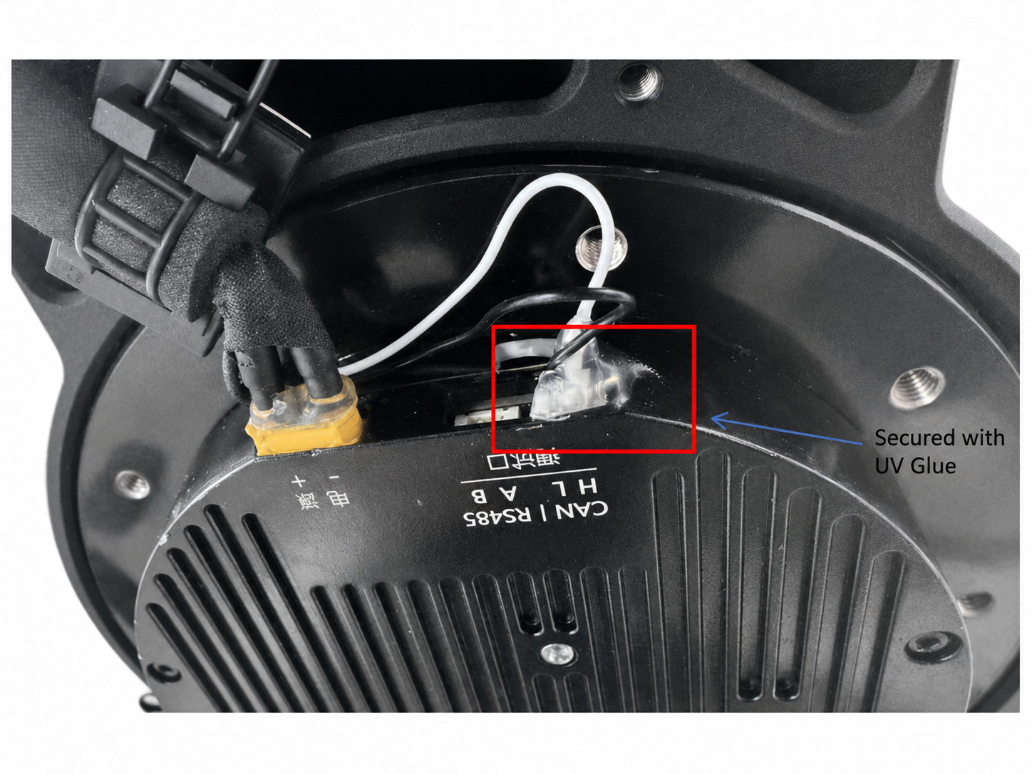
To prevent the CAN port from falling off or breaking during movement, UV glue can be used to reinforce and fix the port.